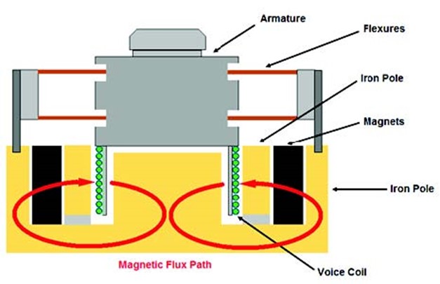
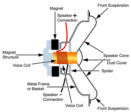
Electrodynamic shakers can basically be thought of as large industrial loudspeakers/voice coils. A voice coil turns the electrical currents into physical vibrations that make the sound waves for your ears to pick up. Electrodynamic shakers are capable of applying very high levels of force.
Electrodynamic shakers move up and down in proportion to the current flowing on the moving structure of the magnetic field formed as a result of the passage of electric current through the windings in the fixed body, and this movement appears as vibration. Thanks to this controllable vibration, vibration life tests and endurance tests of many tools and equipment are carried out.
When selecting an electrodynamic shaker, two key factors need to be considered first:
1. Moving mass
2. Acceleration level
The moving mass refers to the total mass of the armature, the part to be tested and the fixtures and bolts used in the assembly of the test part to the shaker. The acceleration level indicates the value desired to act on the moving mass.
According to Newton’s second law of motion, the product of these two factors allows us to find the force required to perform the test (F=m.a).
The force value can be expressed in Metric units of measurement, kgf, or in imperial units of measurement, lbf’.
To ensure a longer shaker life and to prevent a possible operating error or a damage, using the force of the shaker at 80% capacity as the first step is recommended.
There are three functional limits to electrodynamic shaker performance. These are:
1 ) Displacement
2) Acceleration
3) Velocity
The displacement of an electrodynamic shaker is a function of how far the armature can move up and down. Displacement is higher at low frequencies at constant acceleration and lower at high frequencies in inverse proportion to the increase in frequency. The most common displacement limit for electrodynamic shakers is 51mm (peak-to-peak movement). This means that an armature can move 25mm up and 25mm down from its center position. It is a standard protection method applied by shaker manufacturers to prevent the shaker from damaging the system by over-displacement by using displacement sensors that shut down the system before the mechanical limits of the shaker are exceeded.
Acceleration is generally limited to a value of 100 g in the sine vibration profile for electrodynamic shakers. The acceleration value that can be applied varies according to the shaker force capacity and the weight to be tested. The acceleration values of a vibration test can be determined by the user or specified by standards.
Velocity limits shaker performance between displacement and acceleration limits and refers to the speed at which the moving part of the shaker, the armature, moves, with 2.5m/s being the most common velocity limit.
*Displacement, acceleration and velocity are related terms.
The derivative of displacement with respect to time gives velocity and the derivative of velocity with respect to time gives acceleration.
Frequency
Frequency is a concept that indicates the number of repetitions of an event that occurs within a certain time. If this specific time is taken as 1 second, the unit of the frequency value expressed is Hz.
Frequency is the most common term used in the field of vibration. The method used to make sense of time domain data is conversion to frequency domain.
Electrodynamic shakers operate over a wide frequency range from DC to 3000 Hz. Special seismic grounds are required for testing at frequencies as low as 0.5 Hz. While many test requirements in the automotive and transportation industries emphasize testing below 1000 Hz, vibration specifications, especially in the defense and aerospace sectors, require testing at upper limits of 2000 Hz.
Natural Frequency
Each structure has its own natural frequencies. Natural frequency is the high amplitude and continuous vibration of a structure in response to an external force. Natural frequency is also known as resonant frequency, but if the damping ratio of the structure against the force acting at the natural frequency point is high, the effect of resonance is not seen. Although resonance is generally known as an undesirable, damaging vibration frequency. Since a resonant structure has a much higher response than the applied force, it is not desirable for the vibration fixtures used in vibration tests to have a resonant frequency in the frequency range to be tested.
Electrodynamic shakers have a lot of internal and external equipment. A good knowledge by users of what these equipment are used for and working principles of its operation is essential to ensure correct performance of vibration tests.
Armature
Armature is the part that moves up and down in the magnetic field in electrodynamic shaker systems. There are armatures of different sizes and weights for shakers of different capacities.
– A lightweight armature is more convenient and allows testing at higher g levels.
– The armature must have a high degree of rigidity as it will carry the test specimen and operate dynamically.
– Magnesium or aluminum is usually used as the construction material. Magnesium has a very high weight-to-strength ratio and is the material of choice because it has a high damping.
– Smaller armatures may be suitable for testing smaller products, while larger armatures may not require the use of a head expander, thus reducing the overall system mass. Eliminating the head expander improves transmissibility.
Since the armature is the point of origin of the vibration, it must move in an absolutely centralized manner. For this purpose, the armature is kept in the center position with the support part from the bottom and the alignment parts from the top. These parts and connection types may vary according to brands and models.
Since the shakers have displacement limits, the position of the armature must be known. This position must be set as the midpoint before the test starts so that the armature moves up and down evenly. For this purpose, optical sensors and an automatic/manual air supply/discharge unit are used. Thus, the luminaire will keep its position fixed at the midpoint, with or without load on it.
It is not sufficient or safe to center the luminaire only at the beginning of the test. In advanced systems, the movement of the armature is continuously controlled by sensors while the test is in progress and if it exceeds the displacement limits, mechanical or electronic switches are used to stop the system without damage.
In order to prevent the parts to be placed on the armature from damaging the system, it is desired that the center of gravity should be close to the center of the armature as much as possible. If such a connection is not possible, a bearing system should be added to reduce the lateral loads on the armature. This system is generally applied to head expander systems.
When testing large or multiple products, if the test specimen extends too far from the center of the fixture, the product may be damaged or the test may be performed incorrectly because the vibration transmission will be different.
Head expander provides broader mounting surface area and properly mount the test specimen reduces this potential problem. Head expanders should be designed with the rigidity to transmit vibration without damping. Bolted structures should not be preferred as bolted connections reduce energy transfer.
The preferred material is primarily magnesium or aluminum as in the armature, but steel may be preferred considering factors such as cost and ease of production.
DynaLabs Head Expander structure is magnesium. Thus, it has high strength-to-weight ratios.
The current flowing through the windings on the armature is generated by the amplifier.
Amplifiers are used in many audio systems in daily life. Those amplifiers used for shakers are actually much larger systems.
A force of 1 lbf requires approximately 10 W of power. When we consider this force – power calculation, there are shakers that need power starting from 1000 W to 500kW. Amplifimps below 1000 W need 220V monophase electricity supply.
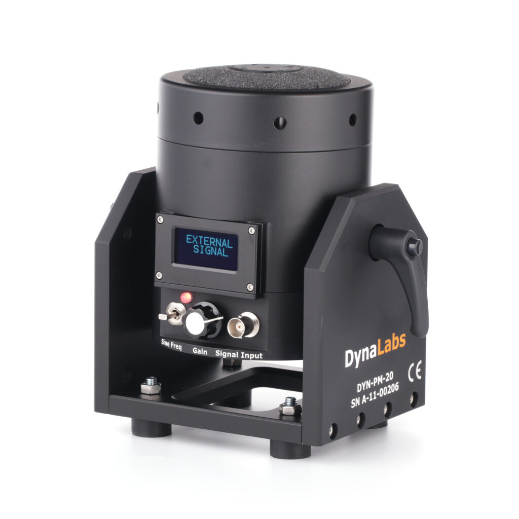
All DynaLabs vibration shakers come included with an amplifier out of the box. For 20N and 100N PM and MS shakers, amplifier is integrated to the shaker.
Shakers consume a significant amount of electricity and this energy is highly converted into heat. For this reason, cooling of the field coils and armature coils is mandatory in electrodynamic vibration systems.
Shakers up to 70kN capacity are typically air cooled.
DynaLabs small PM and MS shakers with integrated amplifiers (20N and 100N) don’t need external cooling system. Passive cooling is enough (natural convection). But for continuous operation at 20N and 100N forced cooling is suggested. For larger shakers (250N and 440N) a blower is needed.
The air cooling unit (blower) used for an air-cooled shaker can be mounted outside the test chamber or remain in the same chamber with sound insulation. Sound insulation is not mandatory, but the noise levels that will occur during the operation of the shaker system are at levels that require the use of earplugs in terms of occupational safety and worker health. The cooler releases the air drawn from the armature into the same room, causing the room to heat up in a shorter time. Due to noise and temperature factors, positioning the cooler outside the room is a generally preferred method.